Your Cart is Empty

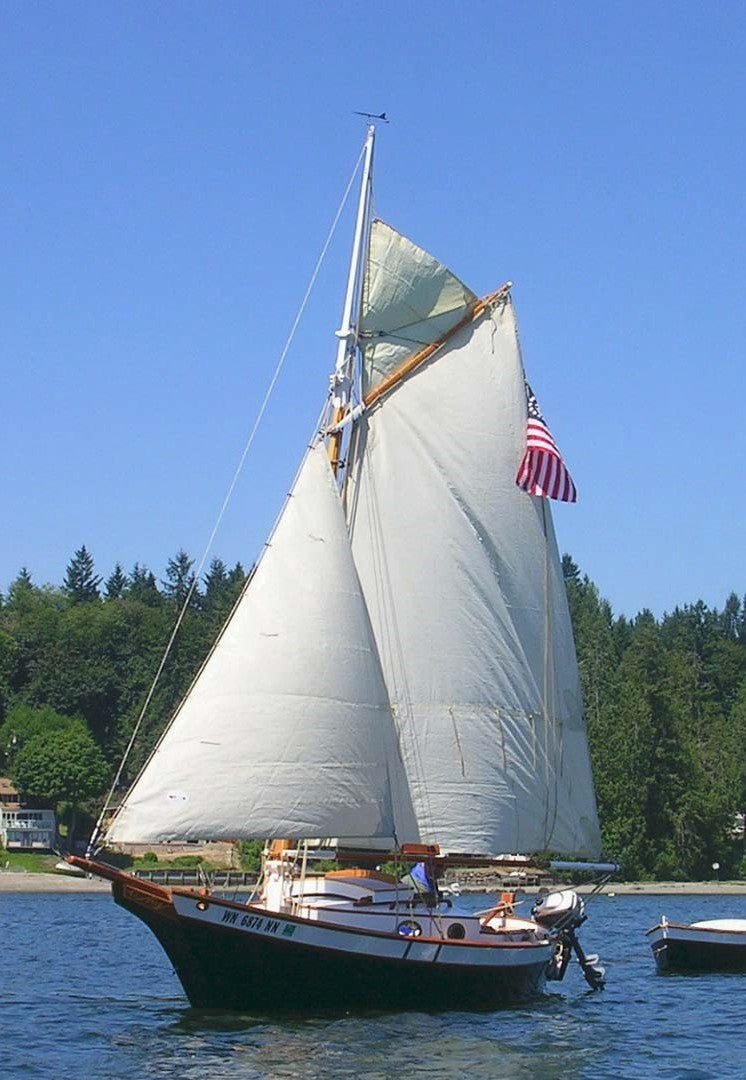
Repair of the Sloop Kaitin from the Outside In
Repair of the Sloop Kaitlin from the Outside In:
A System Three Customer's boat repair in detail
Written by Peter McCowin
"I think the results speak well of the System Three products. The GelMagic adhesive and mixing tips made the job go quickly and allowed me to focus on the repair, and the repair sequence not the adhesive or mixing. On a side note I had been looking for years for a quality satin varnish that will stand up to the Puget Sound weather, System Three Satin Urethane Varnish really filled the bill. It went on uniformly with a uniform satin gloss, and was easy to thin and apply..."

With an undulating impact and subsequent rise and fall of the hull into and out of sight in the rear view mirror, two thoughts flashed to mind: the sloop Kaitlin was not to sail at the 38th Annual Port Townsend Wooden Boat Festival, and that a wooden boat is infinitely repairable. The worst case scenario of boat trailering had just occurred, a rear-end car collision into a stopped trailered boat. The car's impact and continuing movement forward had, among other events, forced the small transom mounted outboard inward toward and under the hull, explosively rupturing the epoxy laminated plywood transom, leaving both the mount and attached outboard motor separated and hanging on a remaining splinter of wood. Where the motor mount had once been attached was now a jagged edged rectangular hole large enough to pass a soccer ball through.
The nature of plywood hull damage is hard to predict with inner ply delaminations occurring in no obvious pattern. The degree and total area affected by an impact, or pull out, can be effected by numerous factors such as total hull thickness, internal framing support, pre-stress bending, manufacturer repair plugs for example.
The configuration of the Kaitlin's hull and transom is such that there is no clear direct access to the inner transom surface other than through a small bilge pump hatch centered low in the aft cockpit wall.
Without clear access and alteration to the aft cockpit wall to gain additional access (not practical) the repair to the hull would need to be completed working from the exterior using mirrors and what limited access view is available.
Regardless of the damage, the first step in the repair would be mapping what is and is not damaged. A determination must first be made as to the extent of the real damage to the transom skin to determine how far the delamination extended beyond the perimeter of the hole edge, or simply, what is still good?
With such limited access, a drawing diagramming out the damage and contour skin thickness remaining was needed to aid in the repair design. From this drawing a repair patch assembly could be developed. Since there is a curve to the transom the repair patch would be assembled from laminations of 6mm plywood allowing for formation of the contour curve back into the repaired structure.
With the full extent of the damage diagrammed, the design and layout of the repair patch could begin. The requirement of the repair was all pieces of the repair would need to be installed through the remaining hole in the repair as patch area became smaller as the patch was assembled. The completed repair would need to provide the strength of the original hull transom as the motor mount would return to the same area.
The repair patch consisted of three ply laminations of 6mm plywood bonded in sequence using System Three Resin's products. Use of the self-mixing tips eliminated concerns in regard to resin to hardener ratios, permitting a focusing on the segmented assembly repair sequence. A final 6mm ply filler layer bonded to the patch outer surface was later surface planned and belt sanded down to match the existing transom surface contour.
The repair was designed such that each 6mm ply layer formed a terraced or stepped lip about the open center perimeter of sufficient width that, when bonded, a full load transfer would occur between the base lamination ply to the fitted center plug ply.
Each 6mm patch layer assembly was developed such that, although several individual pieces assemble together to form the total patch layer, the overlying layer covers the butt joints of the ply below providing no direct load failure path through the total bonded thickness of the repair.
The sequence of the repair can be followed in the following photos and text:

1. Looking aft, access to the transom inner hull surface was limited, available only through a small bilge pump access hatch centered and low in the aft cockpit wall.

2. Where the transom motor mount had been attached was now outlined in a jagged edged delaminated hole outlining the perimeter of the motor mount.

3. The cars impact and continuing movement forward had forced the transom mounted outboard motor propeller drive shaft inward toward and under the hull. With the resulting bending loads causing a rupturing delamination of the plywood around the perimeter of the motor mount.

4. Inspecting the interior hull damage it was clear a significant delamination had occurred in the interior plywood hull extending outward from the perimeter edge of the hole in various degrees of severity.

5. Since the damage to the transom was not directly visible from the interior of the cockpit, key index points were established and thickness measurements taken about the hole. The measurements were then used to develop a contour line drawing representing and mapping the remaining hull thickness and zones of delamination.

6. With the extent of the damage mapped and diagrammed the design layout of the repair patch and sequence of assembly of the patch could begin. Foam board sheet was used to mock up various configurations of each piece which when assembled would form the specific ply repair layer.

7. A Mylar drawing sheet film overlay was placed over the developed contour damage mapping drawing and used to layout and establish each part of the 6mm ply assembly layer developing the sequence of the repair assembly and orientation of each ply layer over lapping joints.

8. Using foam board to mock-up the trimmed hole to be cut in the transom, each patch part was tested for assembly sequence fit through the proposed trimmed hull hole.

9. With the repair patch ply layers and assembly sequenced finalized, the details comprising each ply layer were cut from 6mm plywood and nested together for a fit check.

10. The developed repair cutout pattern was transferred to a Mylar film drawing and, using interior frames for reference, the template was placed into the correct interior position. Holes were drilled at each corner intersection to index the pattern to the outer transom surface.

11. Using the drilled index pin holes, the template was transferred to the outer hull and the perimeter outline marked and cut-out.

12. With the hull repair area cut and trimmed, the remaining delaminated plywood not cut away was repaired using System Three SilverTip GelMagic epoxy adhesive.

13. With the inner skin delaminations repaired, System Three SilverTip GelMagic epoxy adhesive was dispensed using a self-mixing tip and spread evenly on the inner surface of the transom and the inner face of each 6mm ply details in the first ply layer. Each piece was then fit in place, assembled sequentially, and clamped in place forming a complete ply layer.

14. With the epoxy spread evenly, the ply details are assembled and butted up edge to edge with wide throat C-clamps evenly placed about each ply piece.

15. With the epoxy cured, the C-clamps are removed from the assembled first ply along with remaining excess epoxy.

16. To verify a uniform lip overlap between the ply layers, a trial alignment and fit-up was done on the second ply layer assembly.

17. Using a penciled index line to the establish the overlap, System Three SilverTip GelMagic epoxy adhesive was spread evenly on the inner surface of the first applied ply layer and the inner face of each 6mm ply details in the second ply layer. Each piece was assembled sequentially for fit and C-clamped as a complete layer for cure.

18. Wide throat clamps passing through the inner assembled access hole are used to clamp up the second ply assembly.

19. The second ply cured, the clamps were removed, and excess epoxy removed from the created terraced hole.

20. System Three SilverTip GelMagic epoxy adhesive is applied to the lip overlap, contact surface of the center ply plug, and the inner close out. Using temporary #10 pan head wood screws the center plugs are clamped in place forming the assemble plug to the transom contour.

21. With the epoxy cured the temporary fasteners are removed.

22. With the inner plug glued in place, the patch was sealed and closed.

23. The pre-kitted final outer ply insert is uniformly coated on both contact surfaces with a thin layer of System Three GelMagic adhesive. The outer filler ply is then inserted within and aligned to the final thickness build-up ply layer, and is held into the correct contour and flex position using temporary #10 pan head wood screws. With the epoxy fully cured, the temporary screws are removed.

24. With all temporary fastener screws removed, the final plywood filler layer is rough trimmed using a sharp hand-plane, followed by careful belt sanded using various grits to finally match the surrounding contour shape.

25. The repair is further hand-sanded, with remaining small variations and clamp-up mark-off areas filled in and faired in with System Three QuikFair, using a wide blade putty knife to spread and fill remaining gaps. The fairing step is repeated until a smooth faired transom shape is obtained.

26. Faired and smoothed. A single layer of 6oz glass cloth is draped and temporally tacked down and held in place using standard blue masking tape. A thin layer of System Three SilverTip epoxy resin is rolled on and smoothed using a blade wiper. Once cured, the process is repeated until the weave of the glass is completely filled. Once cured the epoxy coated areas are wet and dry sanded smooth and fair.

27. Once sanded, the transom surface is ready for painting. The white trim painted first and allowed to fully dry, then the trim line was taped and the base jade green color panted. Three coats were applied and allowed to fully dry prior to fit-up and mounting of the new outboard motor mounting bracket. A single corner index pilot center point was located and center drilled using the original Mylar drawing to index the new motor mount bracket into the original location.

28. Using the index pilot counter sink to locate the initial hole, the remaining mounting holes are drilled and the new motor mount bracket installed into the original location. The final result produced a repair structurally stiffer than the initial construction and cosmetically completely matching the original fit and finish of the original hull.
1 Response
Leave a comment
Comments will be approved before showing up.


Corbin Haugen
August 31, 2016
Very impressive repair job! Sorry to see such a pretty boat get damaged in the first place but nice to see it restored to original finish.